
Vertical Tanks with IMFO®
 Traditional tank maintenance can be a challenge with many chemicals – so Poly has developed a unique system that helps minimize the hazards associated with traditional vertical tank maintenance.
With Poly’s Integrally Molded Flanged Outlet, or IMFO® system, the flange is molded while the tank is processing, making it a stress-free part of the tank. The flange is created from the same material as the tank – it’s not an insert introduced during or at post-production.
Available with the OR-1000 system
For additional information on IMFO® systems, download the guide. Or, for specific questions about vertical tanks with IMFO®, please contact a Poly Processing chemical storage tank expert.


Advantages of IMFO®
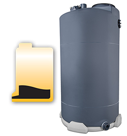
- Since the flange is at the bottom of the tank, full drainage is achieved below the tank knuckle radius, which can eliminate the need to enter the tank for cleaning.
- One-piece construction enhances long-term performance of the tank, since it doesn’t compromise the tank hoop’s integrity or structural design.
- In aggressive applications, the complete flange face is protected by the antioxidant OR-1000™ system.
- The IMFO’s design brings you the highest amount of static head pressure, which contributes to the highest net positive head suction (NPHS) of any vertical non-coned tank.
Looking for Next Level Full Drain Tank Solutions?

Documents
Specifications
Vertical Tanks with IMFO®
Freight:
Choose the factory closest to you for the best freight rates.
NOTE: To view these files, you can use the 3D CAD Viewer or PDF viewer.
Columns in the table below with arrows in the heading can be sorted by clicking the arrows.
| Lugs | Drawings | Gal. Per Inch Chart | Stock | F.O.B. | Nom. Cap. | Approx. O.D. | Approx Height | Lid Size | IMFO Size | Ladder Height | Tank Weight | |
|---|---|---|---|---|---|---|---|---|---|---|---|---|
| L | • | 2D CAD 2D PDF 3D CAD | 1115500 | LA | 15500 | 13'-9" | 16'-5" | 24" | 4" | 16' | 5000 | |
| L | • | 2D CAD 2D PDF 3D CAD | 1113650 | LA, CA | 13650 | 13'-9" | 14' 7" | 24" | 4" | 14' | 4661 | |
| • | 2D CAD 2D PDF 3D CAD | 1112200 | CA | 12200 | 12'-0" | 16'-7 3/4" | 24" | 4" | 15' | 4300 | ||
| • | 2D CAD 2D PDF 3D CAD | 1112150 | LA | 12150 | 12'-0" | 17'-3/4" | 24" | 4"/6"/D | 17' | 4500 | ||
| L | • | 2D CAD 2D PDF 3D CAD | 1110300 | CA | 10300 | 12'-0" | 14'-5 1/4" | 24" | 4" | 15' | 3100 | |
| L | • | 2D CAD 2D PDF 3D CAD | 1110150 | LA | 10150 | 11'-11" | 14'-4 3/4" | 24" | 4" | 14' | 4000 | |
| L | • | 2D CAD 2D PDF 3D CAD | 1108500 | LA | 8500 | 10'-0" | 16'-8 1/2" | 24" | 4" | 17' | 3400 | |
| L | • | 2D CAD 2D PDF 3D CAD | 1108100 | LA | 8100 | 11'-11" | 11'-10" | 24" | 4" | 12' | 2300 | |
| L | • | 2D CAD 2D PDF 3D CAD | 1108050 | CA | 8050 | 10'-0" | 16'-1" | 24" | 4" | 15' | 2600 | |
| L | • | 2D CAD 2D PDF 3D CAD | 1107300 | LA | 7300 | 10'-2" | 14'-1 3/4" | 24" | 4" | 14' | 2100 | |
| L | • | 2D CAD 2D PDF 3D CAD | 1106650 | LA | 6650 | 11'-11" | 10'-1/2" | 24" | 4" | 10' | 1800 | |
| L | • | 2D CAD 2D PDF 3D CAD | 1106600 | CA | 6600 | 10'-0" | 13'-6 1/2" | 24" | 4" | 13' | 1800 | |
| L | • | 2D CAD 2D PDF 3D CAD | 1106150 | LA, VA | 6150 | 10'-2" | 12'-4 3/4" | 24" | 4" | 12' | 1600 | |
| L | • | 2D CAD 2D PDF 3D CAD | 1106115 | LA | 6115 | 8'-6" | 16'-3 3/4" | 24" | 4"/4"/D | 16' | 2030 | |
| L | • | 2D CAD 2D PDF 3D CAD | 1106100 | CA | 6100 | 10'-0" | 12'-7 1/2" | 24" | 4" | 12' | 1550 | |
| L | • | 2D CAD 2D PDF 3D CAD | 1105050 | LA | 5050 | 7'-10" | 16'-1/4" | 24" | 4"/6"/D | 16' | 1650 | |
| L | • | 2D CAD 2D PDF 3D CAD | 1104600 | CA | 4600 | 10'-2" | 9'-6 3/4" | 24" | 4" | 9' | 1450 | |
| L | • | 2D CAD 2D PDF 3D CAD | 1104300 | LA | 4300 | 11'-11" | 7'-1 1/4" | 24" | 4" | 7' | 1100 | |
| L | • | 2D CAD 2D PDF 3D CAD | 1104150 | VA | 4150 | 8'-6" | 11'10 1/2" | 24" | 3" | 12' | 1200 | |
| L | • | 2D CAD 2D PDF 3D CAD | 1104050 | CA | 4050 | 8'-2" | 12'-8 3/4" | 24" | 3" | 12' | 1150 | |
| L | • | 2D CAD 2D PDF 3D CAD | 1103900 | LA | 3900 | 7'-10" | 12'-8 1/4" | 24" | 4"/4"/D | 12' | 1010 | |
| L | • | 2D CAD 2D PDF 3D CAD | 1103000 | VA | 3000 | 7'-1" | 11'-11 3/4" | 24" | 3" | 12' | 900 | |
| L | • | 2D CAD 2D PDF 3D CAD | 1103000L | LA | 3000 | 7'-1" | 11'-11 3/4" | 24" | 3" | 12' | 900 | |
| L | • | 2D CAD 2D PDF 3D CAD | 1102750 | CA | 2750 | 8'-2" | 9'-2 1/2" | 24" | 3" | 9' | 700 | |
| L | 2D CAD 2D PDF 3D CAD | 1102560 | LA | 2560 | 7'-1" | 10'-3 1/2" | 24" | 3" | 10' | 620 | ||
| L | V | 2D CAD 2D PDF 3D CAD | 1102550 | VA | 2550 | 7'-1" | 10'-3 1/2" | 24" | 3" | 10' | 620 | |
| L | 2D CAD 2D PDF 3D CAD | 1102050 | LA | 2050 | 7'-1" | 8'-5 3/4" | 24" | 3" | 8' | 440 | ||
| L | V | 2D CAD 2D PDF 3D CAD | 1102000 | VA | 2000 | 7'-1" | 8'-5 3/4" | 24" | 3" | 8' | 440 | |
| 2D CAD 2D PDF 3D CAD | 1101600 | CA | 1600 | 6'-1" | 9'-1" | 17" | 3" | 9' | 430 | |||
| 2D CAD 2D PDF 3D CAD | 1101400 | LA, VA | 1400 | 5'-4" | 10'-1 1/2" | 17" | 3" | 325 | ||||
| 2D CAD 2D PDF 3D CAD | 1101250 | CA | 1250 | 5'-0" | 9'- 9" | 17" | 3" | 9' | 375 | |||
| 2D CAD 2D PDF 3D CAD | 1101150 | VA | 1150 | 5'-4" | 8'-6" | 17"/19" | 3" | 8' | 260 | |||
| 2D CAD 2D PDF 3D CAD | 1100905 | VA | 905 | 5'-4" | 6'-11 1/2" | 17" | 3" | 6' | 195 | |||
| 2D CAD 2D PDF 3D CAD | 1100850 | VA | 850 | 4'-0" | 10'-5 1/2" | 17" | 3" | 10' | 200 | |||
| 2D CAD 2D PDF 3D CAD | 1100545 | LA, CA | 545 | 4'-0" | 7'-1 1/2" | 17" | 2" | 135 | ||||
| 2D CAD 2D PDF 3D CAD | 1100475 | VA | 475 | 4'-0" | 6'-3 1/4" | 17" | 3" | 140 | ||||
| 2D CAD 2D PDF 3D CAD | 1100325 | VA | 325 | 4'-0" | 4'-7 1/2" | 17" | 3" | 110 | ||||
| 2D CAD 2D PDF 3D CAD | 1100230 | VA | 230 | 3'-2" | 4'-10 3/4" | 17" | 3" | 100 | ||||
| 2D CAD 2D PDF 3D CAD | 1100200 | VA | 200 | 2'-7" | 6'-3" | 7" | 2" | 75 | ||||
|
• = Molded-in lifting lugs L = Molded-in ladder attachment lugs V = Molded-in lifting lugs – Virginia only D = Double IMFO available |
||||||||||||
Polyurethane PolyBase
Columns in the table below with arrows in the heading can be sorted by clicking the arrows.
| Tank Diameter | Stock Number | Drawings | ||
|---|---|---|---|---|
| 2'-7" | 68027000671 | 2D CAD | 2D PDF | 3D CAD |
| 3'-2" | 68032000671 | 2D CAD | 2D PDF | 3D CAD |
| 4'-0" | 68040000671 | 2D CAD | 2D PDF | 3D CAD |
| 5'-4" | 68054000671 | 2D CAD | 2D PDF | 3D CAD |
| 5'-0" | 68050000671 | 2D CAD | 2D PDF | 3D CAD |
| 6'-1" | 68061000671 | 2D CAD | 2D PDF | 3D CAD |
| 7'-1" | 68071000671 | 2D CAD | 2D PDF | 3D CAD |
| 7’10" | 68071000671 | 2D CAD | 2D PDF | |
| 8'-2" | 68082000671 | 2D CAD | 2D PDF | 3D CAD |
| 8'-6" | 68086000671 | 2D CAD | 2D PDF | 3D CAD |
| 10'-0" | 68010000671 | 2D CAD | 2D PDF | 3D CAD |
| 10'-2" | 68010200671 | 2D CAD | 2D PDF | 3D CAD |
| 11'-11" | 68012000671 | 2D CAD | 2D PDF | 3D CAD |
| 13'-10" | 68013100671 | 2D CAD | 2D PDF | 3D CAD |
Crosslinked PolyBase
Columns in the table below with arrows in the heading can be sorted by clicking the arrows.
| Tank Diameter | Stock Number | Drawings | ||
|---|---|---|---|---|
| 4'-0" | 8000004 | 2D CAD | 2D PDF | 3D CAD |
| 5'-4" | 8000054 | 2D CAD | 2D PDF | 3D CAD |
| 7'-1" | 8000071 | 2D CAD | 2D PDF | 3D CAD |
| 8'-6" | 8000086 | 2D CAD | 2D PDF | 3D CAD |
| 10'-0" | 8000010 | 2D CAD | 2D PDF | 3D CAD |
| 10'-2" | 8000102 | 2D CAD | 2D PDF | 3D CAD |
| 12'-0" | 8000012 | 2D CAD | 2D PDF | 3D CAD |
Concrete Pads for IMFO® Tanks
The concrete pad drawings for the IMFO® tanks are for illustration purposes only and should not be used for actual construction. The customer/project engineer should review all information regarding tank installation including seismic and wind restraint requirements, anchor bolt edge distance requirements along with site elevations for pad height. The 6″ notch height/depth shown on the concrete pad illustration drawings is a recommendation and allows a margin of safety for clearance of the largest IMFO® which is 6″ ANSI (11″ diameter). Please contact us at 866-765-9957 for more information.
| PDF Drawing | Pad Type |
|---|---|
| Octagonal Concrete IMFO® Pad | Octagonal Concrete IMFO® Pad |
| Round Concrete IMFO® Pad | Round Concrete IMFO® Pad |
| Square Concrete IMFO® Pad | Square Concrete IMFO® Pad |
PolyBase IMFO and Sloped Bottom IMFO support systems are available for all Vertical Tanks with IMFO and Sloped Bottom Tanks with IMFO. Please contact Poly Processing Company for your PolyBase needs.
For specific questions about vertical tanks with IMFO®, please contact a Poly Processing chemical storage tank expert.